CH32V003 Introduction
A gentle introduction into programming the CH32V003 RISC-V microcontroller.
In this post we will take first steps with the CH32V003 mcu, which is a 32 bit RISC-V mcu based on QingKe RISC-V2A core design by the Chinese company WCH. It supports the RISC-V 32EC instruction set. The post while at its core providing a very simple example will provide you important basic knowledge beyond what is needed to make that example work. I strongly believe that going a bit deeper than just making the example code work will make working with the CH32V003 easier for your future projects.
Required Material
For this article we need a a CH32V003 board that breaks out the gpios from the chip and a programmer to flash our code to the MCU. We use the CH32V003-LinkE Kit for this example. It consists of a CH32V003F4P6-EVT-RO evaluation board, a WCH-LinkE programmer and 5 CH32V003F4P6 MCUs.
You can also get the programmer and the evaluation board individually. For this introduction the additional 5 MCUs will not be used.
Of course you can also use other programmers or dev boards if you know what you are doing, but then maybe this article might be too basic for you.
Setting Up the Development Environment
WCH provides MounRiver Studio, a toolchain and development environment based on Eclipse for RISC-V and ARM cores - mostly targeted at WCHs own chip families. It is available for Windows and Linux. For Mac only the toolchain is provided, but not the full IDE.
That said, for our purpose we are not using MounRiverStudio or the WCH provided toolchain. Rather we are going to use PlatformIO (PIO) with the WCH CH32V platform. As an IDE we are using Microsoft Visual Studio Code (VSCode) but you can use whatever IDE you are using with Platformio.
PlatformIO WCH CH32V Platform and Toolchain Setup
First you need to install VS Code. The website code.visualstudio.com provides an installer for Windows, Mac and Linux. Once the installation is completed, start VSCode.
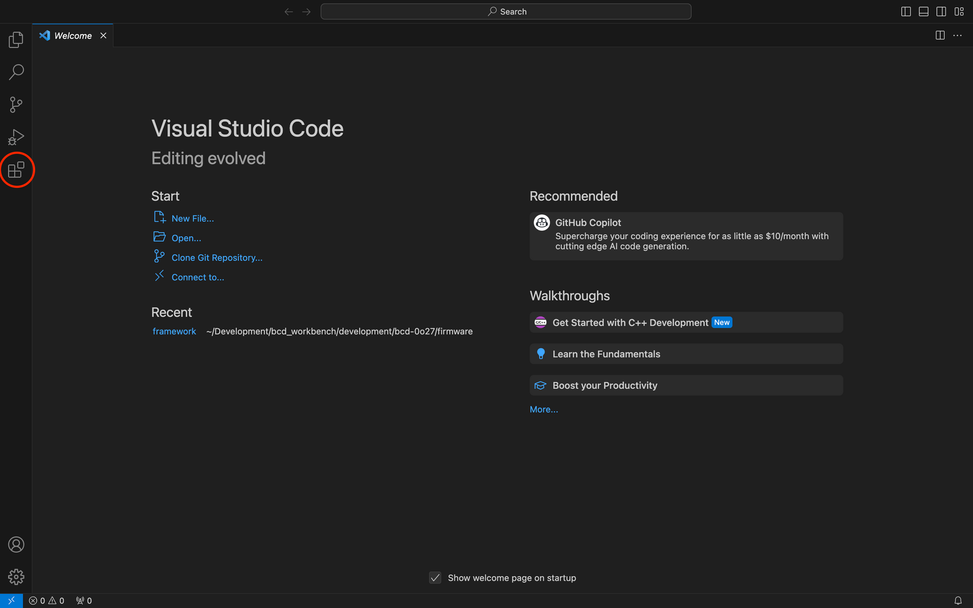
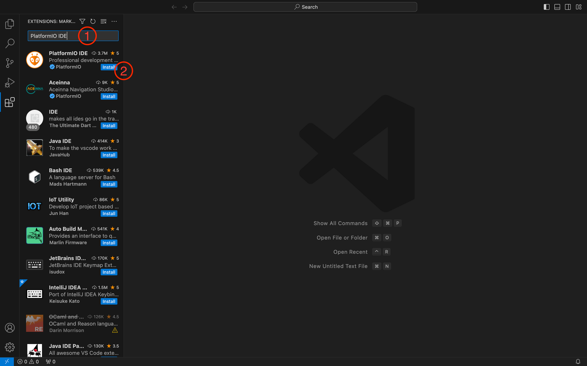
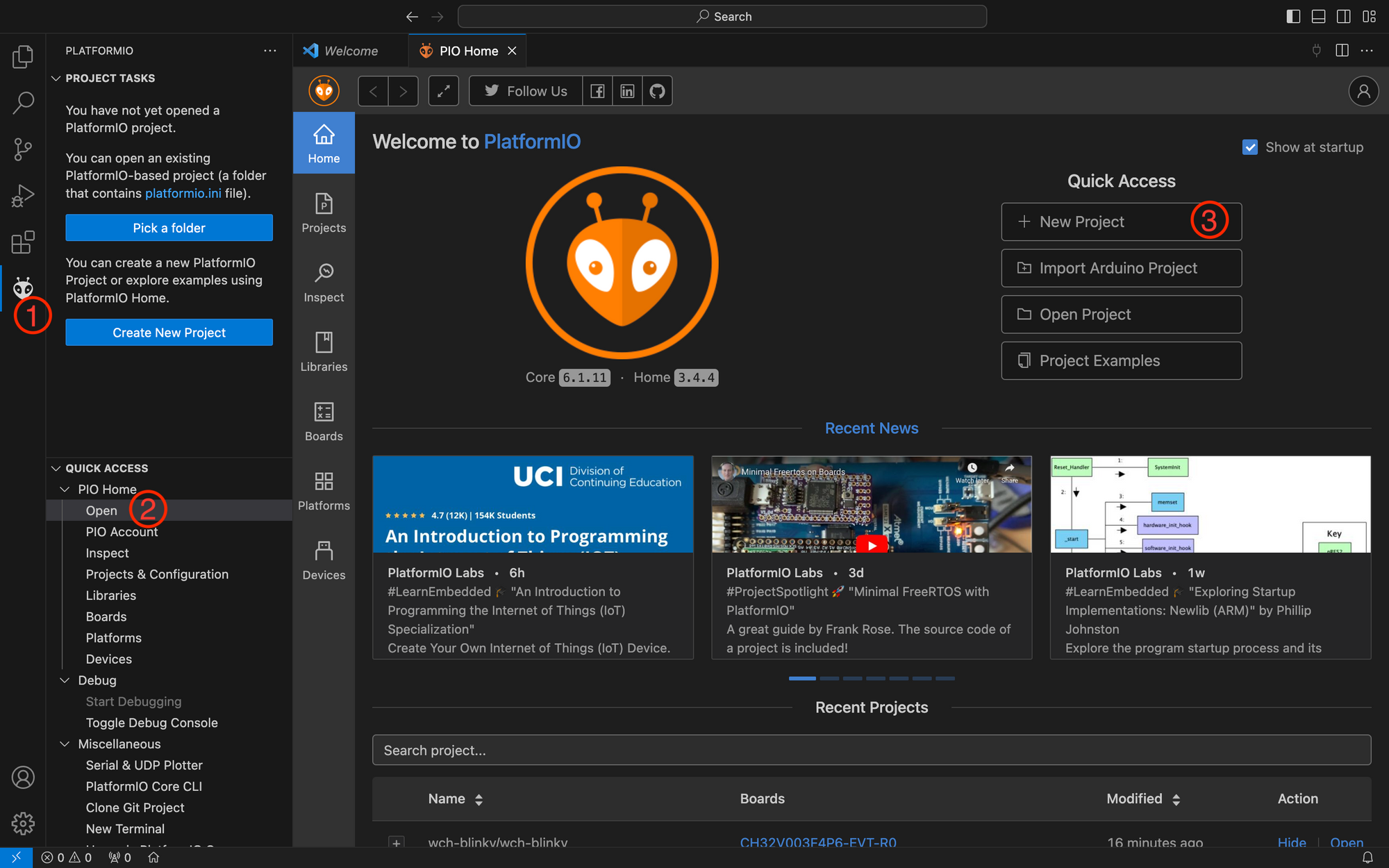
Select the Extensions management in the Activity Bar (icon with four squares in the leftmost bar, marked in the picture above). Then search for the PlatformIO IDE extension and install it by clicking the blue Install button on the bottom left of the PlatformIO IDE list entry.
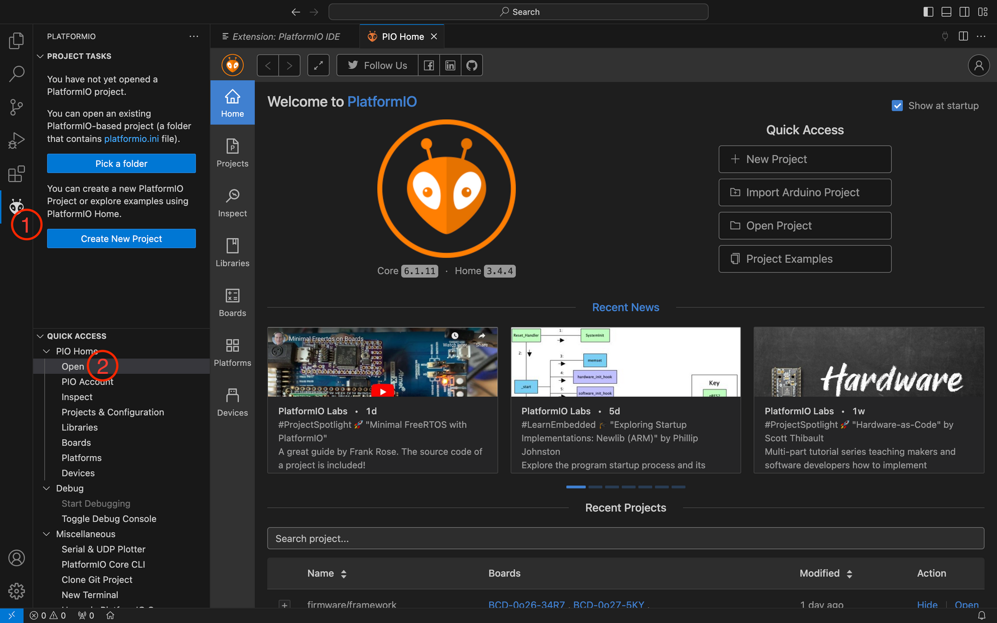
Once installation is complete, there is a new symbol (ant head) in the activity bar. Press the ant head and after a short while, platformio should have initialised properly. Next open PIO Home from the Quick Access menu by selecting Open in the PIO Home tab.
For python it is recommended to install pyenv to be able to switch versions. https://realpython.com/intro-to-pyenv/ is a good guide on how to install pyenv. You then also need to install the python extension in VSCode and follow https://code.visualstudio.com/docs/python/environments#_where-the-extension-looks-for-environments to create a environment for your project. If this sounds too complicated, also the installation as proposed by PlatformIO is fine - but it might lead to trouble later in your development journey if you ever need to deal with multiple python versions.
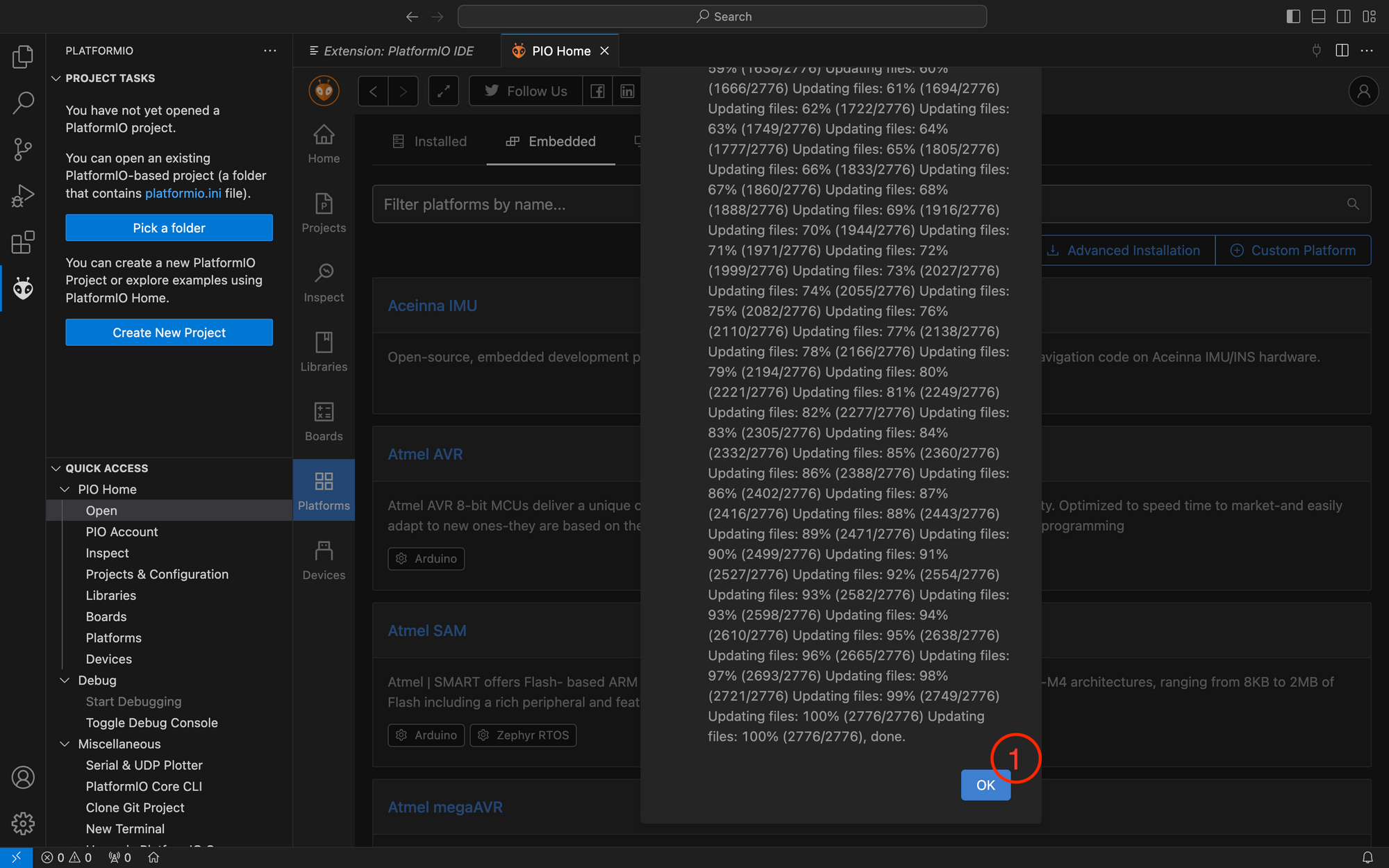
Next you need to install the WCH CH32V platform. To do this open the Platforms manager from the left sidebar in PIO Home. As the platform is not directly available from PlatformIO, you need to install it from the repository of the author. To do so, choose Embedded from the platforms menu bar. Then click on advanced installation.
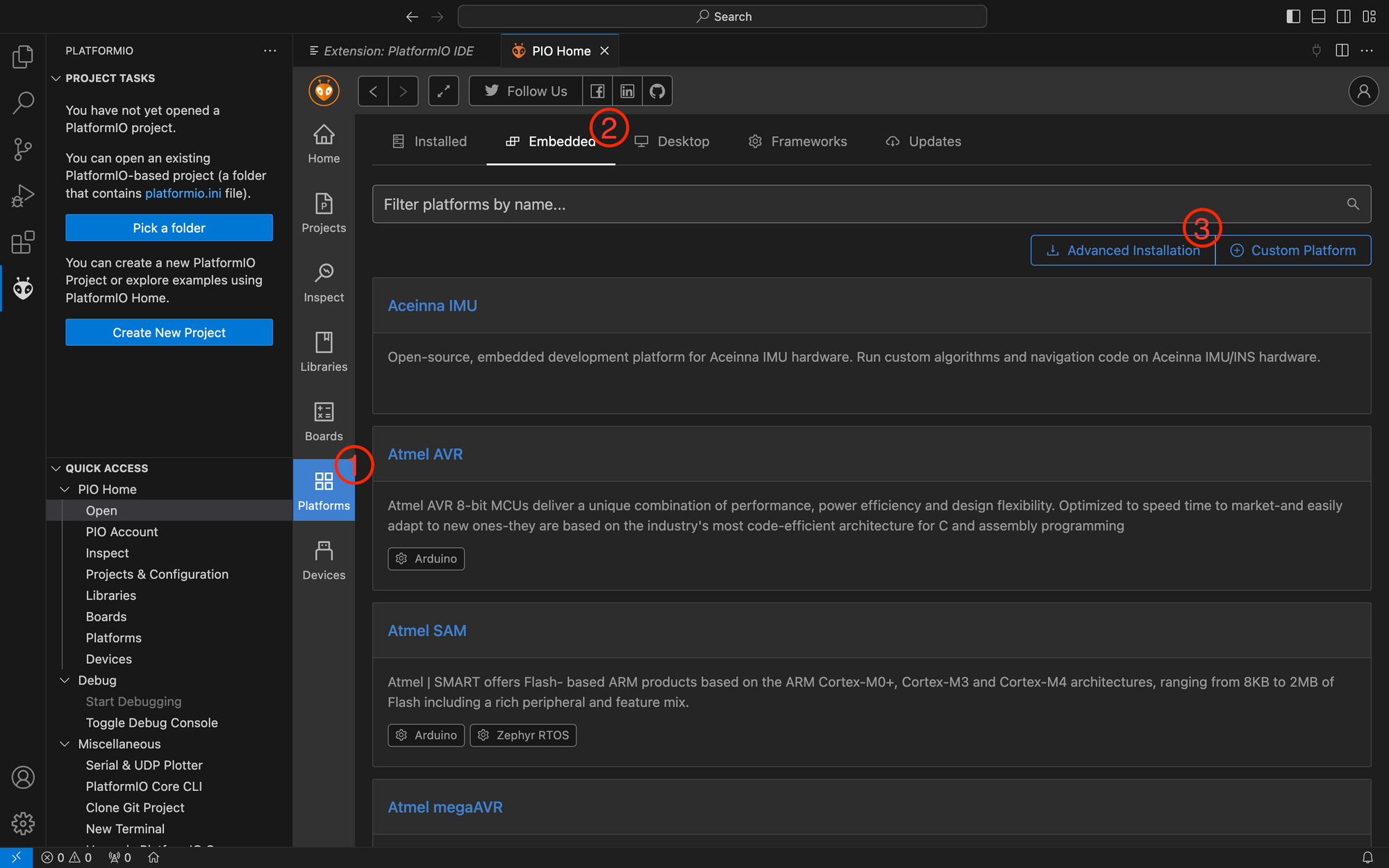
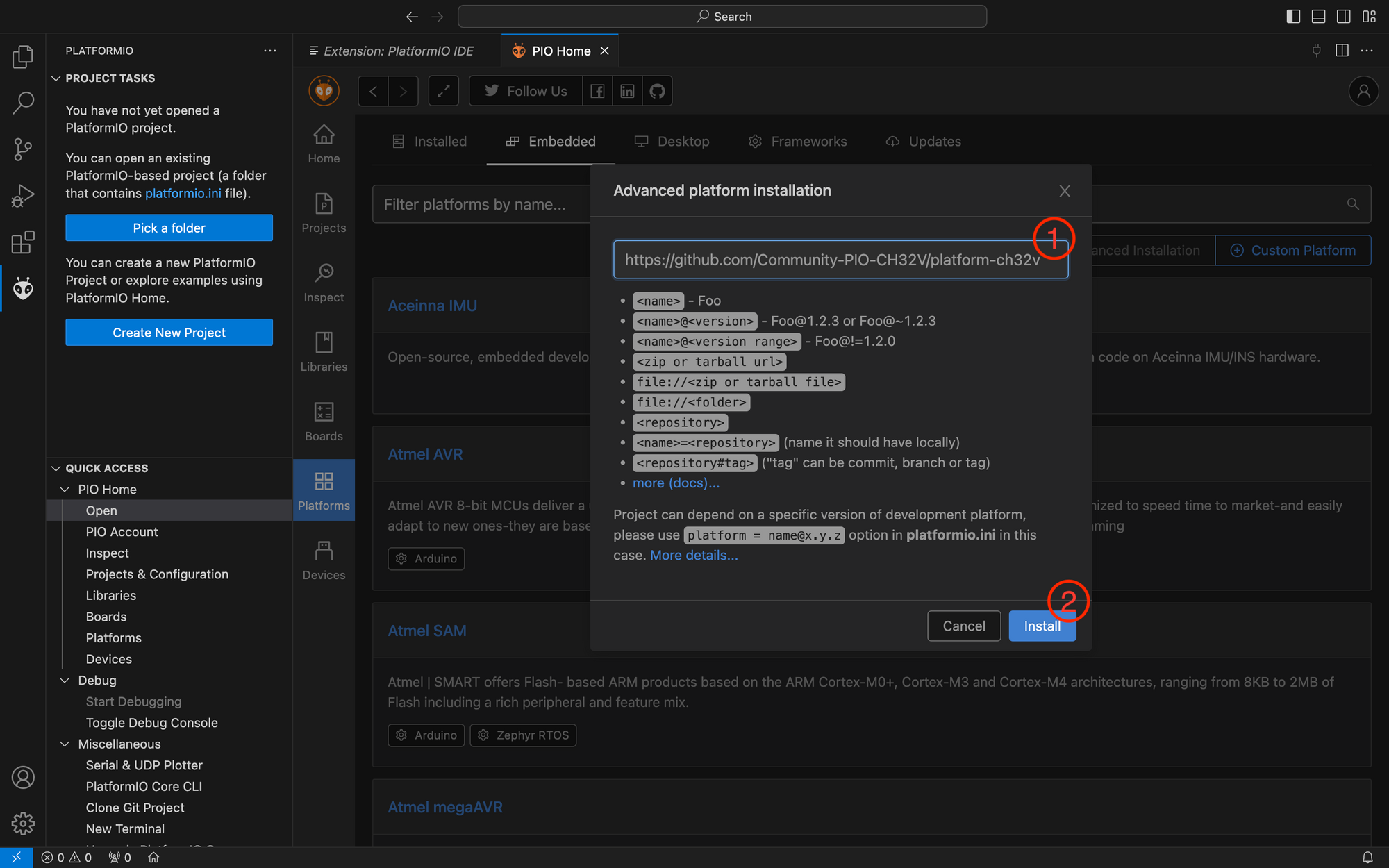
A window pops up where you must enter the repository url https://github.com/Community-PIO-CH32V/platform-ch32v in the text field that asks for Platform name, repository, requirements. Then press the Install button.
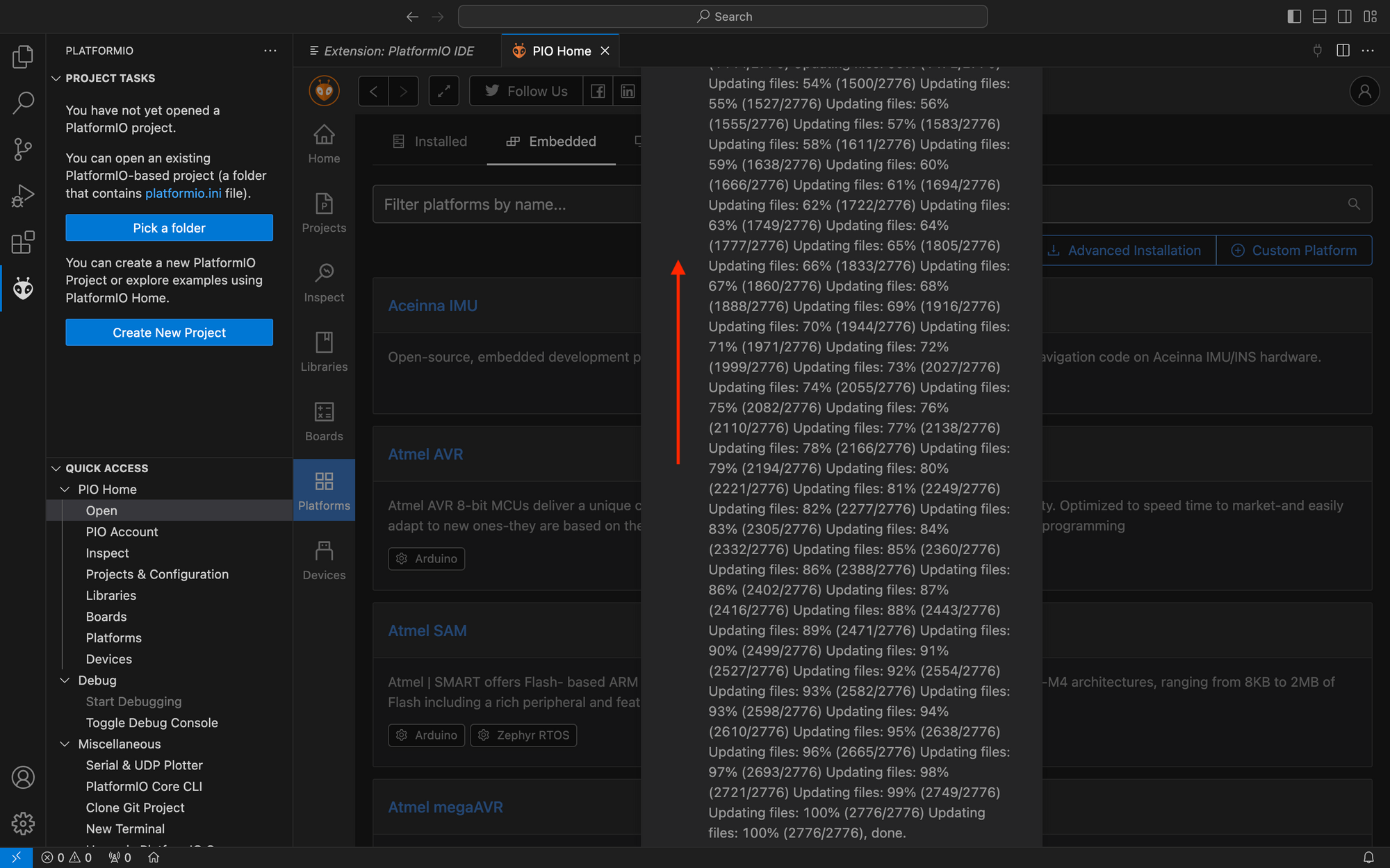
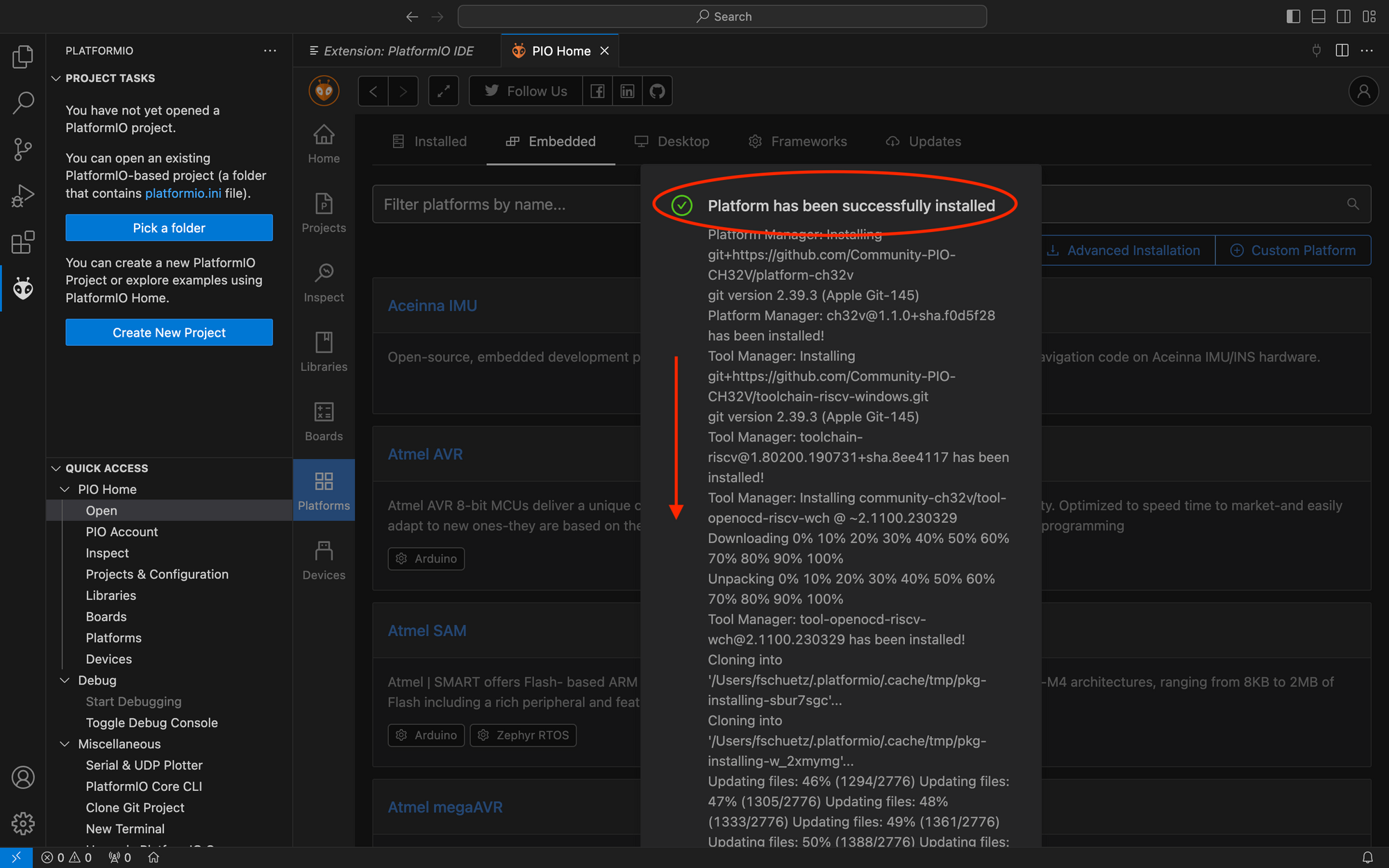
This takes a little while. When the installations is finished, you are greeted by a popup. Likely, there is only text visible. You can scroll the window all to the top where there should be the message "Platform has been successfully installed" next to a green checkmark. Scroll now all the way to the bottom and press the OK button.
If you are using Linux, you also need to set up udev rules to enable non-sudo users to program boards. Follow the chapter 99-platformio-udev.rules in the PlatformIO documentation.
This completes the installation of VSCode, PIO and the WCH CH32V platform.
Setting up the WCH-LinkE Programmer
For Microsoft Windows, you may need to set up the driver for the programmer. Under Linux, you need to set some udev rules. If you are on a mac, you can skip to configuring the hardware in chapter Setting RISC-V Mode.
Installing the Windows WCH-LinkE Driver
First you may want to test if you really need the driver. You can do so by skipping this chapter and coming back if needed. If you decide to feel lucky, move to chapter Setting RISC-V Mode. Alternatively you can open your windows device manager and check that when plugging in the WCH LinkE programmer it shows up as WCH Link (or WCH-Link SERIAL) in Ports and WCH-LinkRV in Interface.
If you want to get the latest version of the official driver, you can download it from the WCH-Link Emulation Debugger website. It is distributed with MounRiver Studio (MRS) and the WCH-Link Utility. Install MRS or unzip the Link Utility and install the driver from its driver folder.
Preferably, you can get the driver at the WCH-CH32V platform git repository. Using this driver only package avoids having to install MRS or WCH-LinkRV, which you likely are not going to use if you follow this tutorial. Unpack the zip file and then run WCHLink\setup.exe and follow the installation instructions. After this run WCHLinkSER\setup.exeand follow the installation instructions.
When driver installation is completed move to chapter Setting RISC-V Mode.
Setting UDEV Rules in Linux
To enable non-sudo users under linux to use the WCH-LinkE programmer you need to set according udev rules. Make sure, that you did set the gerneral udev rules as described in chapter PlatformIO WCH CH32V Platform and Toolchain Setup.
Then (assuming a debian like system with the plugdev group) set the following rules in /etc/udev/rules.d/99-platformio-udev.rule:
SUBSYSTEM=="usb", ATTR{idVendor}="1a86", ATTR{idProduct}=="8010", GROUP="plugdev"
SUBSYSTEM=="usb", ATTR{idVendor}="4348", ATTR{idProduct}=="55e0", GROUP="plugdev"
SUBSYSTEM=="usb", ATTR{idVendor}="1a86", ATTR{idProduct}=="8012", GROUP="plugdev"
If your Linux distro follows a different scheme or you changed your group scheme change it accordingly. You know what you are doing.
Now make sure to restart the system such that the rules take effect.
Setting Risc-V Mode
If a blue led is lit when your WCH-LinkE programmer is plugged in to usb, then it is in ARM mode. It needs to be switched in RISC-V mode. There are three ways to do it:
-
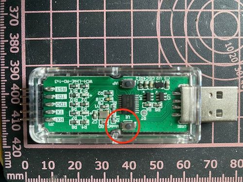
ModeS Key
There is a button labeled ModeS on your programmer. Remove the casing. With your programmer unplugged press and hold the ModeS button and while keeping the button pressed, plug the programmer in your USB port. Once the powerup sequence is complete you can release the button. The blue light should be off, the red light on.
-
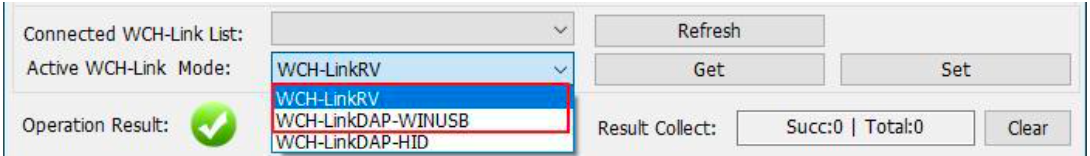
WCH-LinkUtility
Install the WCH-LinkUtility. Click Get on the right side of Active WCH-Link Mode to read the current mode. Then select WCH-LinkRV in Active WCH-Link Mode and click Set.
-
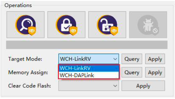
MounRiver Studio (MRS)
Install MounRiver Studio (MRS). Open the project download configuration window (by pressing ). Then click Query on the right side of Target Mode to load the current mode. Switch it to WCH-LinkRV and press Apply.
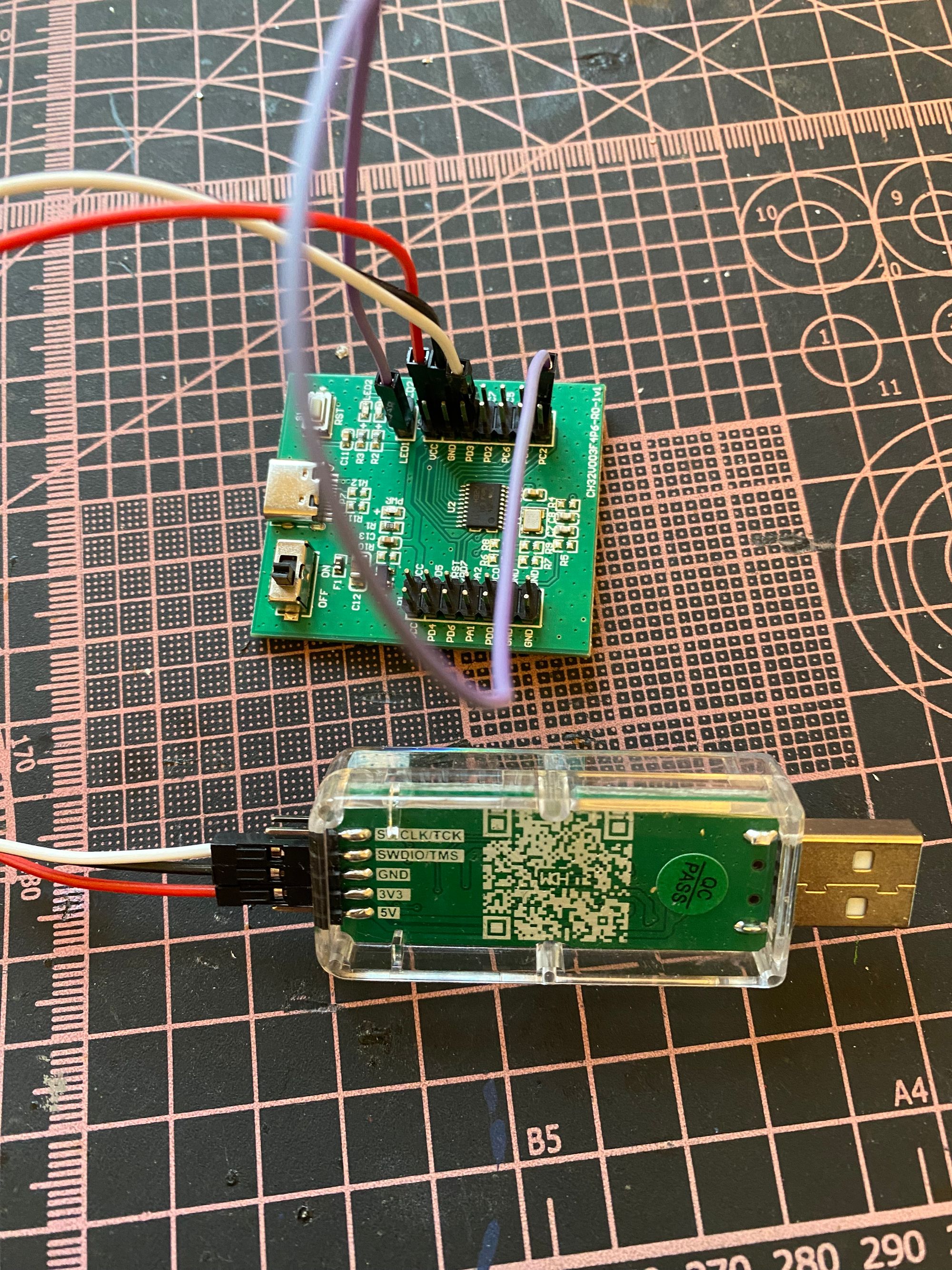
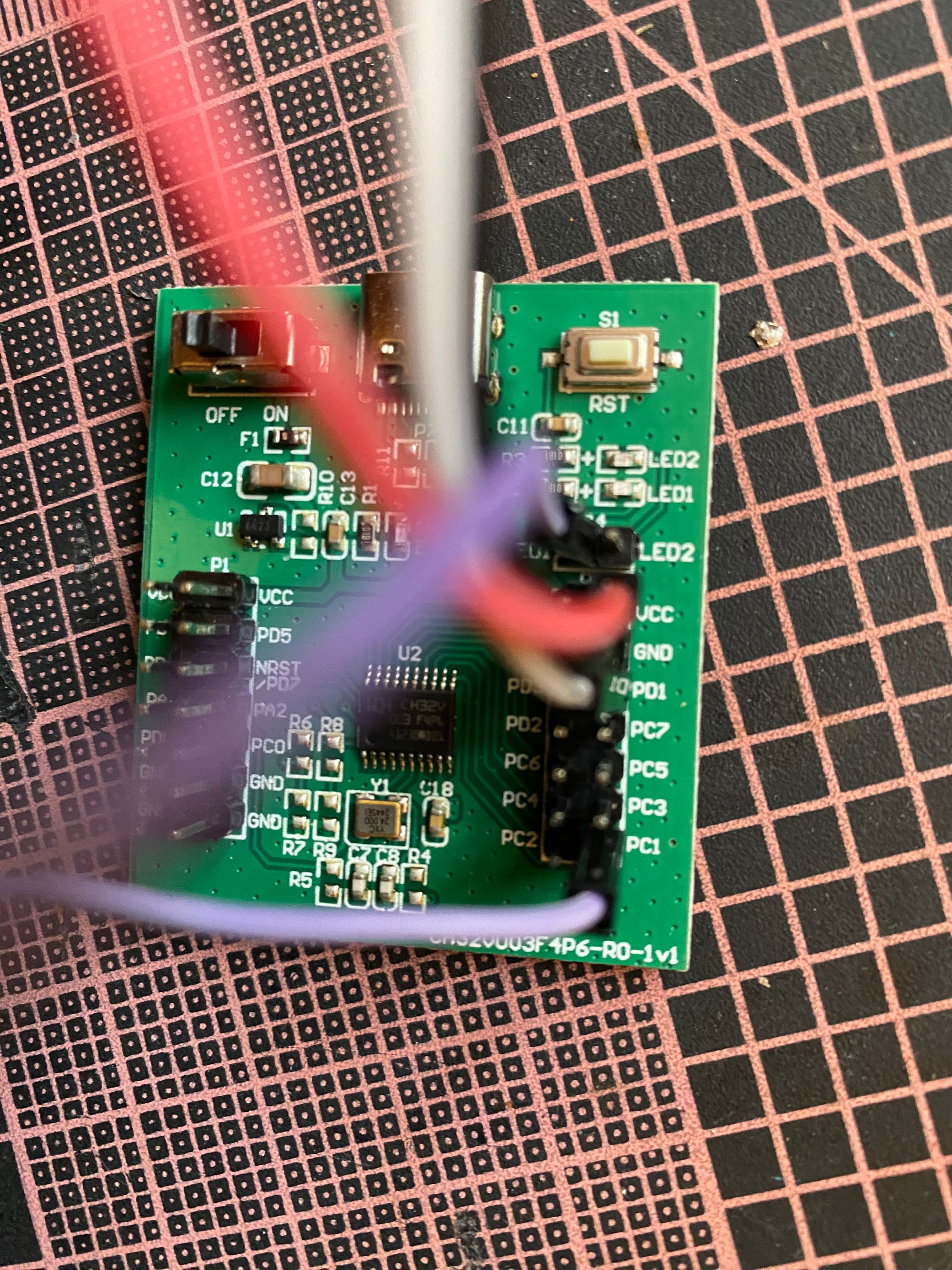
Connecting the Development Board
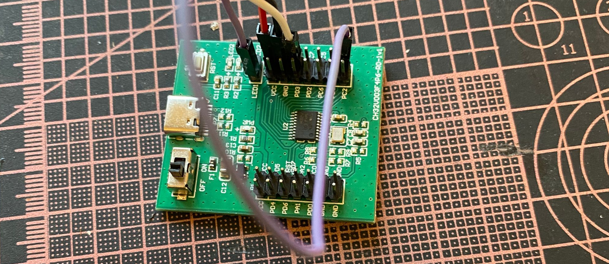
First, on the development board connect the PC1 pin (on the lower right of the right MCU I/O ports poles) to the LED1 pin. This effectively connects GPIO 1 of port C to the first (lower) LED. This is all the connections we need for our demo of blinking the LED.
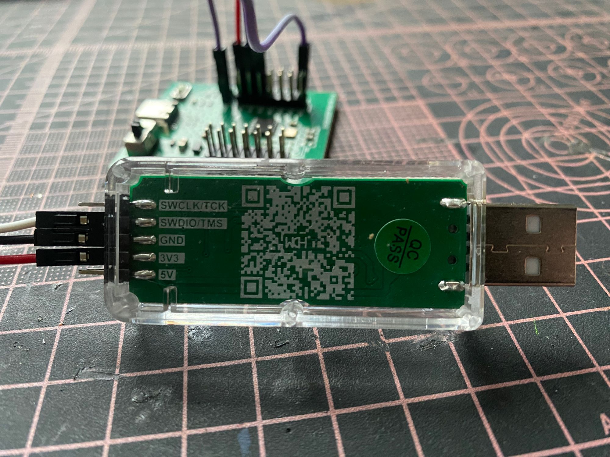
Next, you must connect the programmer to the evaluation board. Connect the 3V3 output pin from the programmer to the VCC pin (upper right pin of the right MCU I/O ports poles) of the development board, the GND pin from the programmer to one of the GND pins of the development board (eg. the pin just below VCC) and the SWDIO/TMS pin of the programmer to the PD1 pin of the development board (just below the aforementioned GND pin).
| From | To | ||
|---|---|---|---|
| Device | Pin | Device | Pin |
| devboard | PC1 | devboard | LED1 |
| programmer | 3V3 | devboard | VCC |
| programmer | GND | devboard | GND |
| programmer | SWDIO/TMS | devboard | PD1 |
Blinking a LED
As no one wants to dive in the details before at least having flashed a led, we will start by writing a small program that flashes a led on the development board. Our simple demo program will blink the LED on the demo board morsing "Hello World". The code will then be discussed in section Closer Look at the Code.
We will start from scratch, generating all files in an empty directory to show the process. After having worked through this example, we will also create some additional directories which allows you to use it as a template in the future.
Starting a New Project
First we need to create a new, blank project for our development board.
In VSCode open PIO Home (choose the ant head in the leftmost menu and then in Quick Access / PIO Home click Open). Select New Project from the Quick Access (on the right of the PIO Home window).
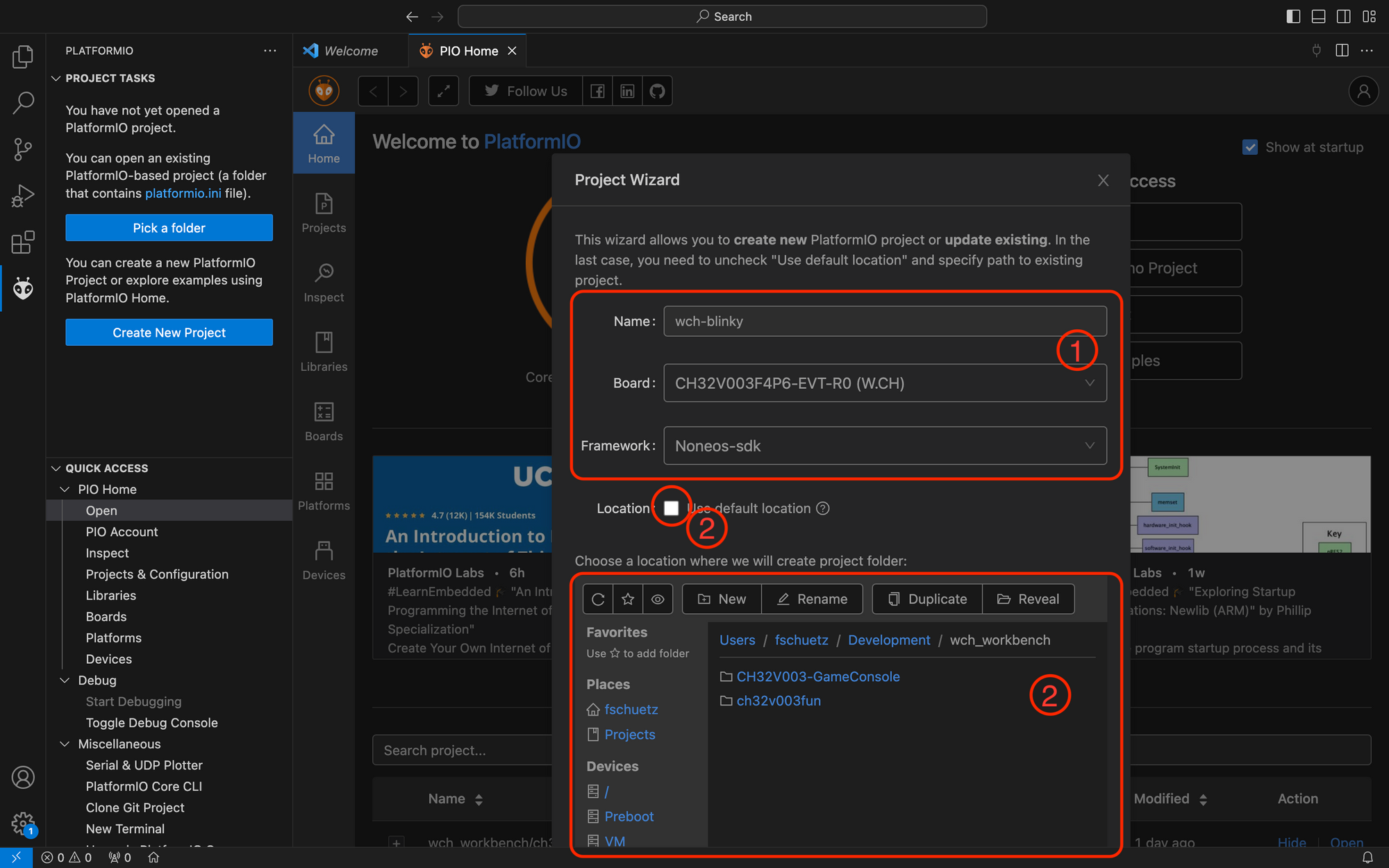
This opens the Project Wizard. Name your project "wch-blinky". For the board select CH32V003F4P6-EVT-R0 (WCH). You can start typing in the field to filter entries. As framework choose Noneos-sdk. This means, we directly program the microcontroller rather than using an abstraction layer / operating system.
You can either create the project in the default location, or choose a folder of your liking. To do so uncheck the use default location checkbox. Then navigate to the top level folder where you would like to create your project. Your project will automatically put in a folder with the same name as your project.
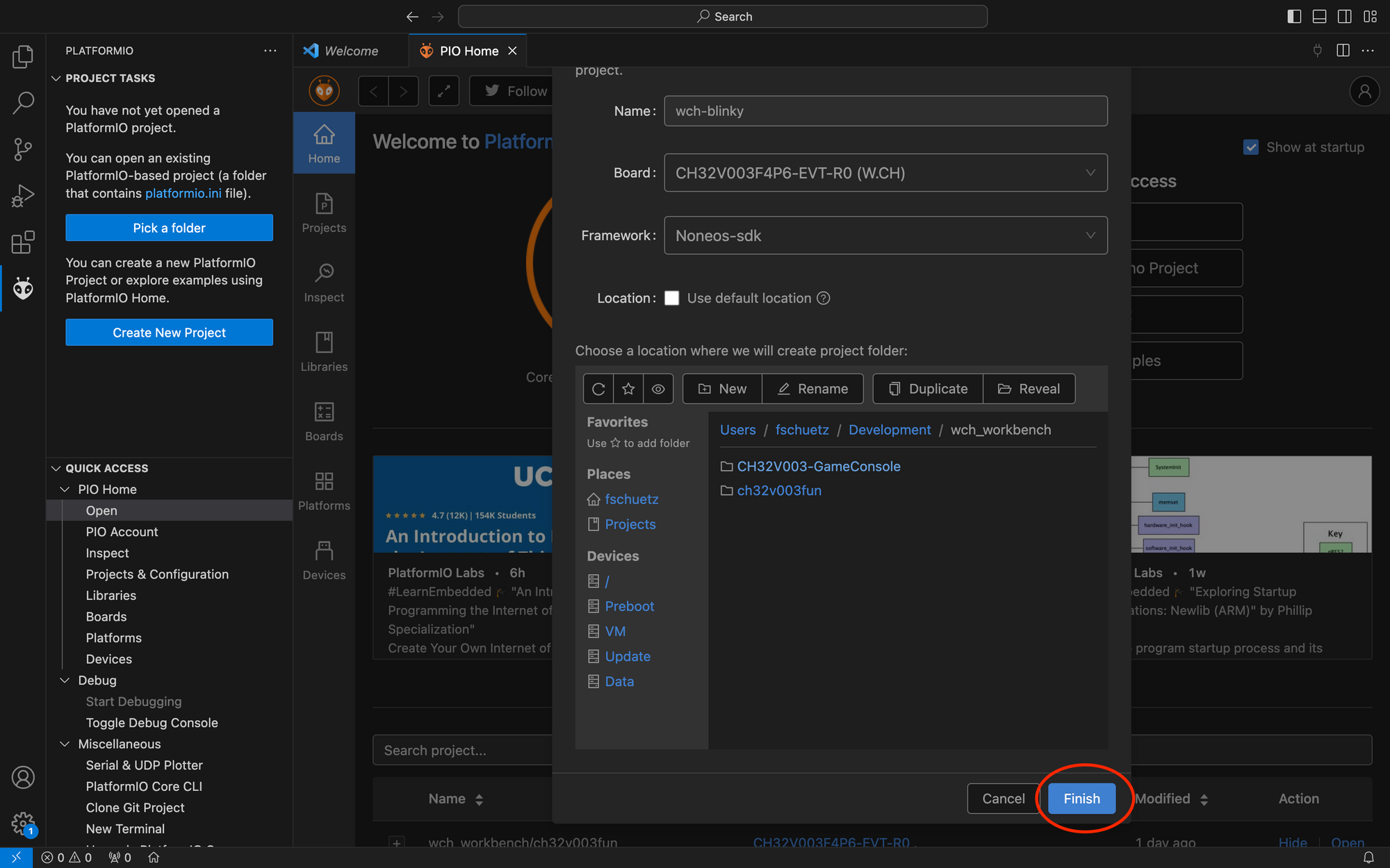
Scroll down and press the Finish button to create the new project.
After a short while the platformio.inifile of your new project will open. On the left, the explorer view will show the generated structure of the project. The following folders and files are displayed:
-
.pio
This folder contains files autmatically created and updated as needed by platformio. Its best to be left alone unless you know what you are doing. -
.vscode
This folder contains files automatically created and updated as needed by VSCode. It is best to be left alone unless you know what you are doing. -
include
This folders purpose in a platformio project is to contain header files. While generally you can put your header files anywhere, putting them in this folder makes them available during compilation. This means in the files where you include the header files from this directory you do not need to specify the path but can simply include it as if it would reside in the same directory (#include "myfile.h"). More detailed information can be found in theREADME. -
lib
This folders purpose is to hold project specific libraries. Platformio will compile libraries in this folder into static libraries and link it into the final execuatable. More detailed information can be found in theREADME. -
src
Your source code goes into this directory. -
test
This folders purpose is to hold your code for testing. -
.gitignore
Every PlatformIO project is initialised with a.gitignorefile which is preset to ignore files from the.vscodeand the.piofolder. Unless you are using git, you can safely ignore or delete this file. -
platformio.ini
This file is the center piece for configuring all aspects of compilation and uploading as well as other parameters for your project. As we used the project wizzard.
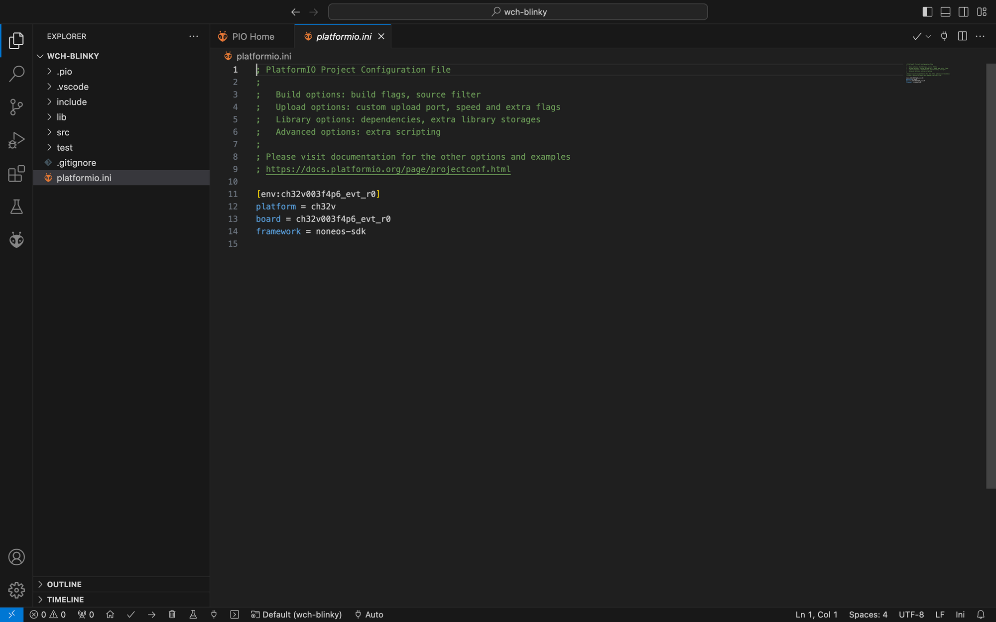
First, wee need to slightly adapt our platformio.inifile. Open it and after framework add a line stating monitor_speed = 115200. This will make sure our serial monitor will be set to the right speed. The serial monitor allows us to read messages sent by the microcontroller over UART to the programmer plugged in our computer. The platformio.inifile should now look like this:
; PlatformIO Project Configuration File
;
; Build options: build flags, source filter
; Upload options: custom upload port, speed and extra flags
; Library options: dependencies, extra library storages
; Advanced options: extra scripting
;
; Please visit documentation for the other options and examples
; https://docs.platformio.org/page/projectconf.html
[env:ch32v003f4p6_evt_r0]
platform = ch32v
board = ch32v003f4p6_evt_r0
framework = noneos-sdk
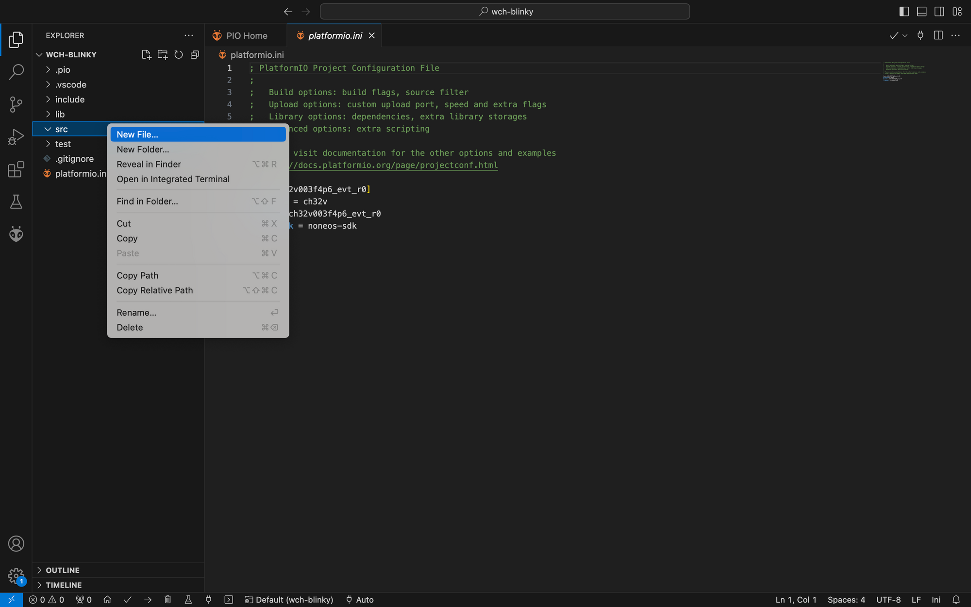
monitor_speed = 115200We also need to create the two files main.c and main.h. Create them in the source folder by right clicking on it and selecting New File (for each file).
Writing the Code
First, we start by writing the main header file main.h. Copy the following code:
/**
 * @file    main.h
 * @author  Florian Schütz (fschuetz@ieee.org)
 * @brief   LED blinking demo for WCH CH32V003 mcu
 * @version 1.0
 * @date    03.11.2023
 *
 * @copyright Copyright (c) 2023 Florian Schütz, released under MIT license
 *
 * This is a short demo how to blink a LED attached to GPIO 1 of port C (PC1)
 * of a WCH CH32V003. The demo is designed to work with the CH32V003F4P6-EVT-RO
 * evaluation board. It will work with any other CH32V003 based setup as long
 * as you have an external clock cristal attached to GPIO 1 and 2 of port A
 * (PA1 / PA2). If you intend to use the internal clock only, then create a
 * custom startup file and set in in platformio.ini as described in
 * https://pio-ch32v.readthedocs.io/en/latest/none%20os%20sdk.html
 */

#include <ch32v00x.h>
#include <debug.h>

// Definitions to allow easy adjustment
#define BLINKY_GPIO_PORT            GPIOC
#define BLINKY_GPIO_PIN             GPIO_Pin_1
#define BLINKY_ON                   0
#define BLINKY_OFF                  1
#define BLINK_LENGTH_MS             100

// Error codes
#define OK                          0
#define ERR_OUT_OF_RANGE            1

/**
 * @brief The main function
 *
 * Initialises the hardware, delays the init and then blinks the LED morsing
 * the message "Hello World".
 *
 * Warning: Do not remove the init delay or you may no longer be able to flash
 *              the chip.
 *
 * @return int Never returns
 */
int main(void);

/**
 * @brief Blinks an led to morse the message
 *
 * This method translates a given message into morse code and blinks a led to
 * display the message.
 *
 * @param msg       The message to be signaled as morse code
 * @param port      The port for the GPIO that has the led attached
 * @param pin       The pin number of the GPIO that has the led attached
 * @param unit_ms   The duration of a unit in milliseconds
 *
 * Function that uses the property of the morse alphabeth that it can be
 * represented as a binary tree. Going left in the tree means we need to
 * write a do, going to the right a dash.
 *
 *                     *
 *               /           \
 *             E               T
 *           /   \           /   \
 *         I       A       N       M
 *        / \     / \     / \     / \
 *       S   U   R   W   D   K   G   O
 *      / \ / \ / \ / \ / \ / \ / \ / \
 *      H V F * L * P J B X C Y Z Q * *
 *
 * If we parse this tree in preorder and list the characters in a sequence
 * (**ETIANMSURWDKGOHVF*L*PJBXCYZQ**), the index for each of these characters
 * has the property that in its binary representation if we start at the most
 * significant bit that is 1, the following bits are encoding the dashes (1)
 * and dots (0) for the character. https://www.pocketmagic.net/morse-encoder/
 *
 * Convention from morse code are:
 *  - The length of a dot is one unit
 *  - The length of a dash is three units
 *  - The space between parts of the letter is one unit
 *  - The space between letters is three units
 *  - The space between words is seven units
 */
int morse(const char *msg, GPIO_TypeDef* port, uint32_t pin, uint32_t unit_ms);

/**
 * @brief Handler for non-maskable interrupts (nmi)
 *
 * Non-maskable interrupts (nmi) are interrupts that the mcu canot ignore and that
 * need to be attended to immediately. In our mini blinky example, the nmi
 * handler will just do nothing. Who really cares if we crash and burn.
 */
void NMI_Handler(void) __attribute__((interrupt("WCH-Interrupt-fast")));

/**
 * @brief Fault handler
 *
 * Faults are errors that occure during runtime. An example would be a NULL
 * pointer derefference. This handler for our blinky example will just enter
 * and infinite loop, effectively thorwing the system to non action in ever
 * lasting limbo.
 */
void HardFault_Handler(void) __attribute__((interrupt("WCH-Interrupt-fast")));
Next we need to write the implementation in main.c. Copy the following code:
/**
 * @file    main.c
 * @author  Florian Schütz (fschuetz@ieee.org)
 * @brief   LED blinking demo for WCH CH32V003 mcu
 * @version 1.0
 * @date    03.11.2023
 *
 * @copyright Copyright (c) 2023 Florian Schütz, released under MIT license
 *
 * This is a short demo how to blink a LED attached to GPIO 1 of port C (PC1)
 * of a WCH CH32V003. The demo is designed to work with the CH32V003F4P6-EVT-RO
 * evaluation board. It will work with any other CH32V003 based setup as long
 * as you have an external clock cristal attached to GPIO 1 and 2 of port A
 * (PA1 / PA2). If you intend to use the internal clock only, then create a
 * custom startup file and set in in platformio.ini as described in
 * https://pio-ch32v.readthedocs.io/en/latest/none%20os%20sdk.html
 */
#include "main.h"

/**
 * @brief The main function
 *
 * Initialises the hardware, delays the init and then blinks the LED morsing
 * the message "Hello World".
 *
 * Warning: Do not remove the init delay or you may no longer be able to flash
 *              the chip.
 *
 * @return int Never returns
 */
int main(void) {

    // Configure priority grouping
    //
    // 2 bits for pre-emption priority and 2 bits for subpriority.
    NVIC_PriorityGroupConfig(NVIC_PriorityGroup_2);

    // Update system core clock update
    SystemCoreClockUpdate();

    // Initialise the delay function
    Delay_Init();

    // Initialise UART printf
    USART_Printf_Init(115200);

    // Enable the high speed peripheral clock
    //
    // For APB2 peripheral GPIOC
    RCC_APB2PeriphClockCmd(RCC_APB2Periph_GPIOC, ENABLE);

    // Initialise GPIO
    //
    // To initialise the GPIO pin and port defined for outputting the blink
    // signal we need to populate a structure of type GPIO_InitTypeDef by
    // setting the pin, mode (output) and the speed (50MHz). We then call
    // GPIO_Init with the port defined in the header and the init structure
    // as arguments.
    GPIO_InitTypeDef GPIO_InitStructure = {0};
    GPIO_InitStructure.GPIO_Pin = BLINKY_GPIO_PIN;
	GPIO_InitStructure.GPIO_Mode = GPIO_Mode_Out_PP;
	GPIO_InitStructure.GPIO_Speed = GPIO_Speed_50MHz;
	GPIO_Init(BLINKY_GPIO_PORT, &GPIO_InitStructure);

    // Set the message to blink as morse code
    const char *msg = "Hello World";

    // Morse the message indefinitely
    while(1) {
        printf("Hello World!\n");
        if(morse(msg, BLINKY_GPIO_PORT, BLINKY_GPIO_PIN, BLINK_LENGTH_MS)
            != OK) {
            printf("An error occurred: Invalid message.\n");
        }
        Delay_Ms(1000);
    }
}

/**
 * @brief Blinks an led to morse the message
 *
 * This method translates a given message into morse code and blinks a led to
 * display the message.
 *
 * @param msg       The message to be signaled as morse code
 * @param port      The port for the GPIO that has the led attached
 * @param pin       The pin number of the GPIO that has the led attached
 * @param unit_ms   The duration of a unit in milliseconds
 *
 * Function that uses the property of the morse alphabeth that it can be
 * represented as a binary tree. Going left in the tree means we need to
 * write a do, going to the right a dash.
 *
 *                     *
 *               /           \
 *             E               T
 *           /   \           /   \
 *         I       A       N       M
 *        / \     / \     / \     / \
 *       S   U   R   W   D   K   G   O
 *      / \ / \ / \ / \ / \ / \ / \ / \
 *      H V F * L * P J B X C Y Z Q * *
 *
 * If we parse this tree in preorder and list the characters in a sequence
 * (**ETIANMSURWDKGOHVF*L*PJBXCYZQ**), the index for each of these characters
 * has the property that in its binary representation if we start at the most
 * significant bit that is 1, the following bits are encoding the dashes (1)
 * and dots (0) for the character. https://www.pocketmagic.net/morse-encoder/
 *
 * Convention from morse code are:
 *  - The length of a dot is one unit
 *  - The length of a dash is three units
 *  - The space between parts of the letter is one unit
 *  - The space between letters is three units
 *  - The space between words is seven units
 */
int morse(const char *msg, GPIO_TypeDef* port, uint32_t pin,
    uint32_t unit_ms) {

    // The encoded alphabeth of the binary tree
    const char *alphabeth = "**ETIANMSURWDKGOHVF?L?PJBXCYZQ??";

    // Pointer to character that is currently processed.
    const char *current_char = msg;

    // Indicator if previously processed character was a whitespace.
    uint8_t prev_was_whitespace = 0;

    // The loop encoding and blinking the message
    while(*current_char != '\0') {

        char c = *current_char;

        // Check if the current character is a space. If yes, we need to pause
        // for an additional four units (we already paused three due to pause)
        // beween characters.
        if(c == ' ' || c == '\t' || c == '\n' || c == '\r') {
            // Only delay for one whitespace, ignore if previous character was
            // whitespace as well
            if(prev_was_whitespace == 0) {
                Delay_Ms(4 * unit_ms);
                prev_was_whitespace = 1;
            }

            // Process next character.
            current_char++;
            continue;
        }

        // If we reach here, the character is not a whitespace and we can reset
        // the whitespace indicator
        prev_was_whitespace = 0;

        // Convert character to uppercase if needed
        if(c >= 'a' && c <= 'z') {
            c -= 32;
        }

        // Check if our (potentially converted) character is valid. If it is
        // not we abort with an error.
        if(c < 'A' || c > 'Z') {
            return ERR_OUT_OF_RANGE;
        }

        // Find the index of the position of the character in our encoded
        // alphabeth and convert index in long and short led pulses
        uint8_t index = 0;
        while(alphabeth[++index] != c);

        uint8_t mask = 0b10000000;
        uint8_t i = 0;

        // Search the leftmost bit that is 1 (and ignore it)
        //
        // Note: We omit testing i for <8 as we know the index must contain
        // at least one 1 indicating the encoding start.
        while((((index << i) & mask)) == 0) {
            i++;
        }

        // Now convert 0 to dots and 1 to dashes
        //
        // Note: We do not check i > 0 && i < 8 initially as we know we
        // have at least one digit after the indicator above.
        while(++i < 8) {
            if((index << i) & mask) {
                // dash
                GPIO_WriteBit(port, pin, BLINKY_ON);
                Delay_Ms(3 * unit_ms);
                GPIO_WriteBit(port, pin, BLINKY_OFF);
            } else {
                // dot
                GPIO_WriteBit(port, pin, BLINKY_ON);
                Delay_Ms(unit_ms);
                GPIO_WriteBit(port, pin, BLINKY_OFF);
            }

            // Pause one unit before next symbol
            Delay_Ms(unit_ms);
        }


        // Pause before next letter. We already waited one unit from the
        // blinking of the letter, so we need to wait for two more to
        // have the pause between letters correct.
        Delay_Ms(2 * unit_ms);

        current_char++;
    }

    return OK;
}

/**
 * @brief Handler for non-maskable interrupts (nmi)
 *
 * Non-maskable interrupts (nmi) are interrupts that the mcu cannot ignore and that
 * need to be attended to immediately. In our mini blinky example, the nmi
 * handler will just do nothing. Who really cares if we crash and burn.
 */
void NMI_Handler(void) {}

/**
 * @brief Fault handler
 *
 * Faults are errors that occure during runtime. An example would be a NULL
 * pointer derefference. This handler for our blinky example will just enter
 * and infinite loop, effectively thorwing the system to non action in ever
 * lasting limbo.
 */
void HardFault_Handler(void) {
    while (1) {
    }
}
Compiling and Uploading
Now its time to compile and upload the code. You could just start to upload the code, this will automatically trigger recompilation if needed. However, for the sake of completeness we will first compile the code and then upload it.
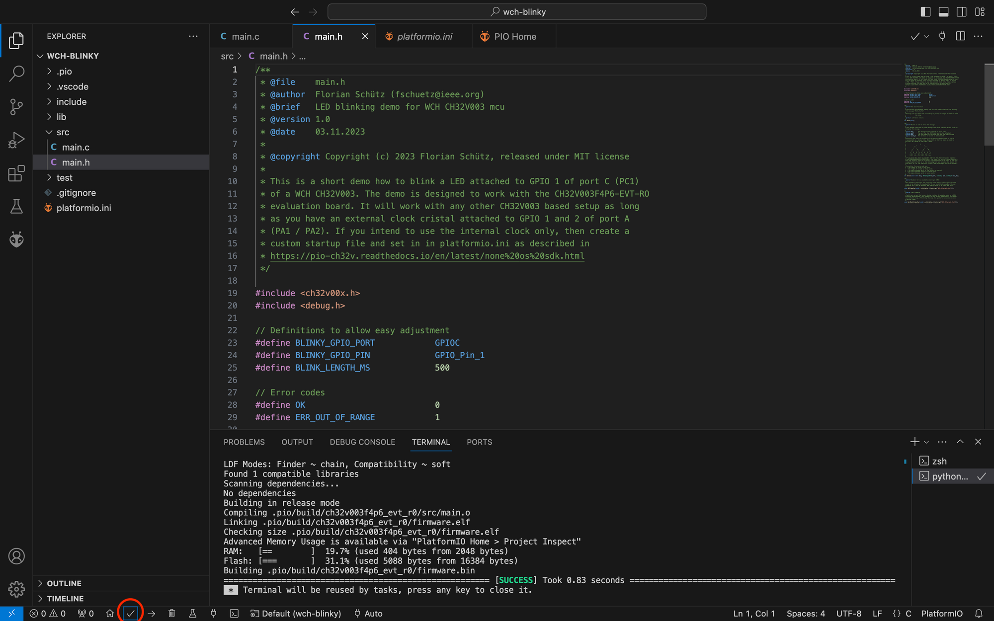
To compile the code choose the checkmark in the lower quick access bar. Alternatively you can open the PlatformIO menu in the left sidebar and in Project Tasks choose ch32v003f4p6_evt_r0->Build.
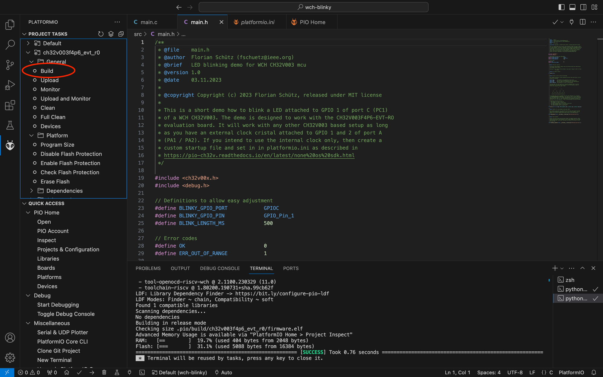
Blinky Compilation
If all went well, you should see a green success message in the terminal (together with an indication how long the compilation took). If you encountered any error or warning (which you should not if you copied the code above) you can scroll up in this terminal to find the error / warning message and take actions to correct it.
In this case you need to install Rosetta 2, which will allow your mac silicone to execute intel binaries. Open a terminal and run the command /usr/sbin/softwareupdate --install-rosetta --agree-to-license.
Another important information that is displayed is the usage of memory, namely the random access memory (RAM) and the flash memory. The CH32V003 comes with 2048 bytes of RAM and 16384 bytes of flash memory. If your program gets too big, it does no longer fit in the flash memory and this will produce an error, as well as if your program uses to much RAM (stack and heap) it will not be able to run successfully.
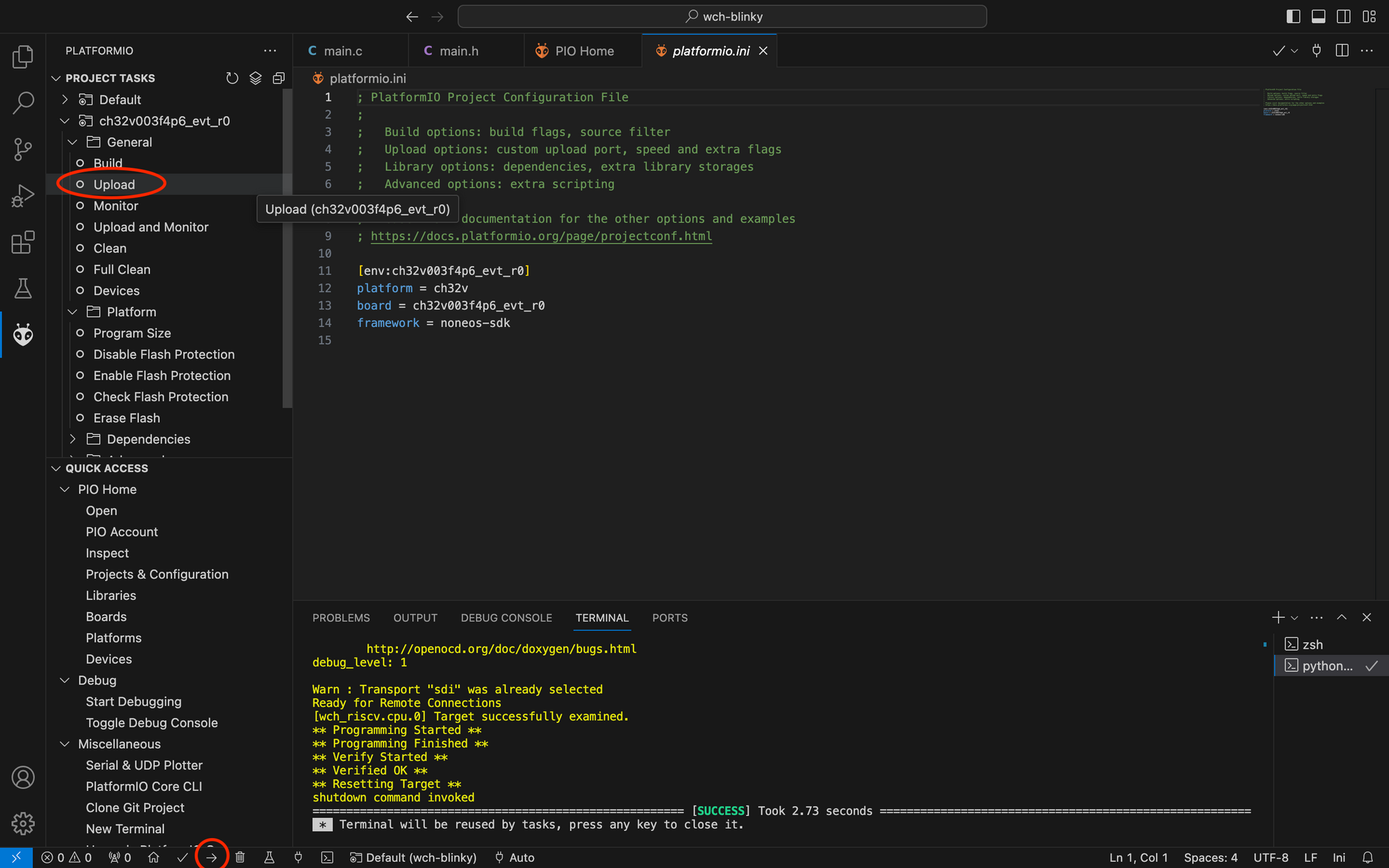
After compilation it is time to upload the code. Make sure the programmer is properly plugged in the usb port and connected to the development board as described in chapter (Connecting the Development Board)[#connecting-the-development-board]. Then start the upload by selecting the right pointing arrow in the lower quick access bar. Alternatively you can open the platformio menu in the left sidebar and in Project Tasks choose ch32v003f4p6_evt_r0->Upload.
The led on your development board should now continuously morse "Hello World". Feel free to change the unit blinking time in main.h to play with the speed or experiment with other parameters in the code. Maybe change the "Hello World" message?
Closer Look at the Code
Now that we compiled and run our first program on the WCH CH32V003 let us take a closer look at the code. We will start discussing the hardware abstraction layer, non-maskable interrupt handler and hard fault handler which we need to set up to get everything up and running. Then we will look at the program entry point and discuss the code that makes the led blink. We will focus on the code that allows us using the GPIO of the mcu to toggle the led and not explain the logic how to translate a sentence to morse code. The explanation of the algorithm is given in the comments of the code.
Hardware Abstraction Layer
A hardware abstraction layer (HAL) is a set of software routines that abstracts access to hardware. For example, if you want to set a general purpose input output (GPIO) to high, you need to first set registers in the mcu to configure the pin where the GPIO state is to be output and then you need to set registers to set the output pin to low (see chapter 7 of the CH32V003 reference manual for more details). The hardware abstraction layer provides higher level routines that make it easier to configure the GPIO ports and output logic state on a pin.
As we stated above, we use the WCH CH32V003 Platform for PlatformIO which provides a full programming framework including a HAL. Therefore, the code and its discussion is dependent on this framework and while the low level statements about the MCU apply under any conditions the routines and definitions in the code do only apply to this framework. So if you use another framework (for example CH32V003fun by CNLohr, which we might discuss in a future article) this may all differ.
We start our main.h header file by including the ch32v00x.h header file. This file provides an access layer for peripherals of the CH32V00X mcu family and must be included at all times.
Interrupts and Fault Handlers
In this section we will not dive in all details of interrupts and faults handling for the CH32V003, but rather discuss the things we ned to set up at minimum to get any program, like our blinky, running.
The Nested Vector Interrupt Controller (NVIC) is responsible to halt regular processing, switching to prioritised processing and resuming normal processing once prioritised processing is done. Prioritised processing is needed when an interrupt or a fault occurs.
Non-maskable interrupts (nmi) are interrupts that the mcu cannot ignore an that need to be attended to immediately. Assume that the system time is provided by an external clock. In CH32V003 speak this is called the "High Speed External" (HSE) clock. Using an external clock allows for more precise system timing. If this external clock fails the mcu can detect this error and it will switch to the "High Speed Internal" (HSI) clock, which is less accurate. Then the mcu triggers a non-maskable interrupt to let you know what happened and take corrective action if needed. Whenever a non-maskable interrupt is raised, the nmi handler is called. In the WCH CH32V003 Platform for PlatformIO, the nmi handler function is called NMI_Handler and must be provided by the programmer. It takes no arguments (void) and should get the attribute __attribute__((interrupt("WCH-Interrupt-fast"))).
The attribute WCH-Interrupt-fast enables hardware preamble / epilogue (HPE) functionality. This functionality saves the hardware registers of a processor before entering the interrupt service routine and restores them after exiting the interrupt service routine. This means, that we do not need to do this in our interrupt handler and in general using HPE is faster (unless the interrupt handler is very simple). If you are interested in more details, there is an interesting thread about HPE performance on the CH32V003 on the eevblog.
We did define the NMI_Handler towards the end of the main.h header file you find the definition for the function handling the non-maskable interrupts.
void NMI_Handler(void) __attribute__((interrupt("WCH-Interrupt-fast")));And towards the end of the main.c file we implemented the nmi handler. As our example is only for demonstration purpose, we do not really care about handling any non-maskable interrupt. Our implementation therefore simply does nothing.
void NMI_Handler(void) {}If you are developing more advanced code you should check the CH32V003 reference manual if the peripherals you use can trigger non-maskable interrupts and then handle them in the nmi handler.
Hard faults are faults are abnormal interruptions that cannot be handled by any other exception handling mechanism. A hard fault can be triggered by an illegal instruction or for example by dereferencing a NULL pointer. If a hard fault occurs the mcu will execute the hard fault handler. In this handler you may for example produce a core dump before halting the mcu.
In the WCH CH32V003 Platform for PlatformIO, the hard fault handler function is called HardFault_Handler. It takes no arguments (void) and must have the attribute __attribute__((interrupt("WCH-Interrupt-fast"))). At the end of the header file you find the definition for handling faults.
void HardFault_Handler(void) __attribute__((interrupt("WCH-Interrupt-fast")));And at the end of the main.c file you find its implementation.
void HardFault_Handler(void) {
    while (1) {
    }
}
In our simplistic blinky example we simply put the mcu in an infinite loop if we encounter a hard fault. As stated above, in a real program, you might want to do something like creating a core dump to allow reconstructing what happened.
Debug Output
Proper debugging using PlatformIO with the WCH-LinkE programmer is fully supported by the WCH CH32V Platform, but for simple programs or quick checks using printf to display state can be more efficient. In our example we enable debug output through the UART. If we include debug.h in our main.h header file we can use a preconfigured redirection of printf to print to UART1. The pin used for transmitting is PD5, the pin used for receiving is PD6 (but we don't use this in this example).
Before we can use printf(...) commands for debugging, we need to initialise the UART and specify the baud rate we use. This is done in the main function in main.c with the following code:
    // Initialise UART printf
    USART_Printf_Init(115200);
After that, all output from the printf function will be redirected to UART and can be monitored with a terminal.
To be able to read what the CH32V00 prints to UART, you need to connect the RX pin from your WCH-LinkE programmer to the PD5 pin on the development board.
You can now open the serial monitor in PlatformIO while everything is attached. The serial monitor can either be opened by clicking the plug symbol in the bottom quick access menu or by choosing ch32v003f4p6_evt_r0->monitor in Project Tasksin the PlatformIO menu (ant head in leftmost menubar).
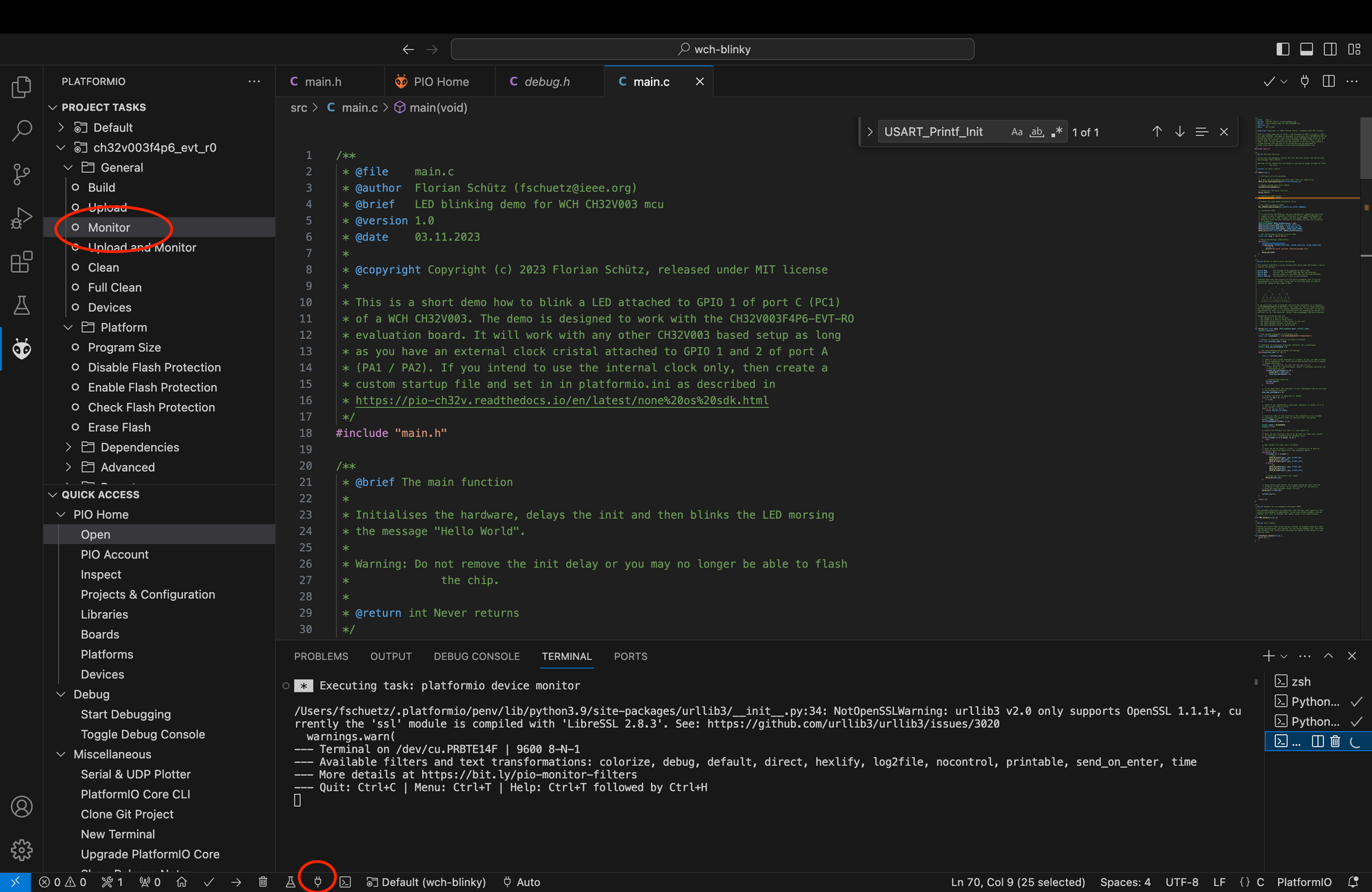
If everything is properly attached and the code on the chip is executed you should see a "Hello World!" message every time the morse code starts anew. If the morse code function encounters an error it will print "An error occurred: Invalid message.".
Clocks and Delays
The CH32V003 mcu provides an internal clock but can also be operated with an external clock. The development board we use provides an external clock on pin 5 (PA1) and pin 6 (PA2). During startup of the mcu we need to select whether we want to use an external clock source or the internal clock source and set its frequency. The WCH CH32V platform automatically sets our mcu to use an external clock at 48MHz by running a so called startup code. This works well with our development board. If you use another board without external clock or you want to change your clock settings you need to adapt the startup code. Chapter Startup Code explains how to do this. The call to SystemCoreClockUpdate(); updates the SystemCoreClock variable with our settings. We have to call this at the beginning of our code to initialise the clock properly.
We need our LED to be on or off for a certain amount of time before switching it again. In our simple example this is easiest to achieve if the MCU simply does nothing for the defined amount of time. At the lowest level, the MCU is not aware of the concept of seconds, minutes and other units. The MCU just knows cycles. How long a cycle takes depends on the clock frequency. As we know we use the external clock at 24MHz (preconfigured by the framework as we told it we use the development board in the platformio.inifile), we could calculate how many cycles a millisecond, second or any other measure of time takes. Luckily, someone already took care of this and defined routines that allow us to delay for microseconds (using the function void Delay_Us(uint32_t n)) or milliseconds (using the function void Delay_Ms(uint32_t n)). Before using any of these functions we need to initialise them calling void Delay_Init(void). We do this in the main.c file with the following line of code:
// Initialise the delay function
    Delay_Init();
After this we use the delay function giving the desired amount of delay as an argument. An example of this is our infinite loop in the main function that after having morsed the message delay for 1 second (= 1000 milliseconds).
    // Morse the message indefinitely
    while(1) {
        if(morse(msg, BLINKY_GPIO_PORT, BLINKY_GPIO_PIN, BLINK_LENGTH_MS)
            != OK) {
            printf("An error occured: Invalid message.\n");
        }
        Delay_Ms(1000);
    }
When using morse code, the convention is that dashes, pauses between characters and pauses between words are a multiple of the duration of a dot. We therefore conveniently define the basic time for a dot in the main.h header file.
#define BLINK_LENGTH_MS 500The code then just uses this value as a base for the delay function and depending on the timing needed multiplies it with the multiplier defined in the convention for morse code. This means, if you want your morse code to be slower or faster, you can simply adapt this base value in the header file.
GPIO Usage
General purpose input / output (GPIO) are inputs and outputs that can be used for different purpose. In our case we want to toggle the GPIO pin of the chip which has the led connected low or high to switch the led on or off.
Before we can use a gpio, we need to configure it. For this we must populate the GPIO_InitTypeDef structure. This is done in the following code snippet:
GPIO_InitTypeDef GPIO_InitStructure = {0};
GPIO_InitStructure.GPIO_Pin = BLINKY_GPIO_PIN;
GPIO_InitStructure.GPIO_Mode = GPIO_Mode_Out_PP;
GPIO_InitStructure.GPIO_Speed = GPIO_Speed_50MHz;
GPIO_Init(BLINKY_GPIO_PORT, &GPIO_InitStructure);
The first line simply initialises the structure with all 0 values. On the second line we set the GPIO pin we want to configure to the pin that is connected to the LED. We then need to set the mode of the gpio and its speed. A GPIO can either be an input or an output. There are two different output modes: Open drain output ( GPIO_Mode_Out_OD ) and push pull output (GPIO_Mode_Out_PP). If a GPIO is used as an input, there are four different input modes: Floating input (GPIO_Mode_IN_FLOATING), pull-up input (GPIO_Mode_IPU), pull-down input (GPIO_Mode_IPD) and analog input (GPIO_Mode_AIN). Open4Tech has a article on different pin configurations that explains the different modes.
The GPIO can also be configured as "alternate function". In this case, the GPIO is no longer general purpose, but used for a specific hardware function like for example pulse width mudulation (PWM) or serial peripheral interface (SPI). The modes for alternate functions can be open drain (GPIO_Mode_AF_OD) or push-pull (GPIO_Mode_AF_PP).
For our purpose we need a push-pull output configuration and thus set the GPIO_Mode field to GPIO_Mode_Out_PP.
Last but not least, we must set the fastest speed supported by the GPIO. There are three possible settings: 2Mhz, 10MHz and 50MHz. We set our GPIO to 50MHz.
Then its time to initialise the hardware by calling GPIO_Init with the port and a reference to the init structure.
After a GPIO has been initialised, we can set it by calling GPIO_WriteBit(GPIO_TypeDef *GPIOx, uint16_t GPIO_Pin, BitAction BitVal). The first parameter is port of the GPIO to be set, the second the pin and the third whether to set it high (1) or low (0). Note that on our devboard, the GPIO acts as ground for the LED. Thus setting the pin low lights the led (current can now flow from the high potential of VCC to the low potential at the pin) and setting it high makes it deactivate (as the potential on both sides of the led is now the same an thus no current flows).
The CH32V003F4P6-EVT-RO Development Board
In this chapter we take an in depth look at the CH32V003F4P6-EVT-RO development board. WCH provides information about the board on its website under the link https://www.wch.cn/downloads/CH32V003EVT_ZIP.html.
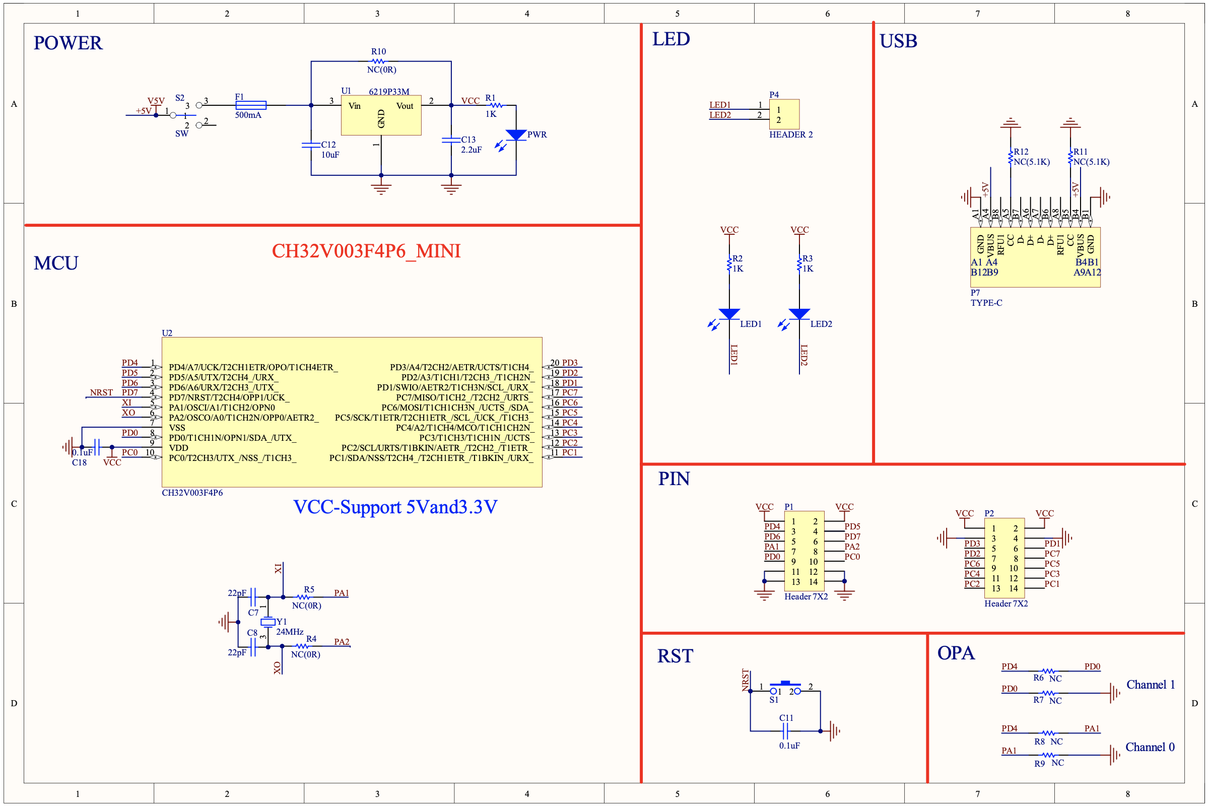
As can be seen in the schematic in there are seven main parts to the development board: The power section, the MCU section, the LED section, the USB section, the PIN section, the RST section and the OPA section.
The MCU section shows the pinout of the MCU and the timer circuit. We will not discuss the MCU in detail in this article. What we need to discuss is the timer circuit, as it is important to understand which restrictions it brings to how you can use the development board. The 24MHz timer crystal Y1 is connected to pin 5 (PA1) and pin 6 (PA4) of the MCU. It provides an external clock source. This means, that those pins cannot be used for anything else. This is why the resistors R5 and R6 are not connected (NC). If you want to disconnect the external clock and use PA1 and PA4 for other things (eg. as GPIO), you need to solder a 0Ω resistor at R5 and R6 (or be creative and bridge it with solder). You should also desolder Y1, C7 and C8.
The power section simply regulating the 5V power from the USB connector to a constant value and indicating through the PWR led that the external power supply is on. The switch can be used to enable or disable power through USB. It is important to note, that the VCC pins from the PIN section are connected to the output of the regulator. This means the board can either be powered through USB or through the VCC pins (for example by connecting the programmer). It must never be fed from both power sources at the same time! Also, if you use USB power you can get the regulated power from the VCC pins to power other components you use, unless you draw too high currents. Unfortunately I did not find a datasheet of the regulator so I do not know its specs.
The LED section is rather simple. The anodes (+) of each led is connected through a resistor to VCC and the cathodes (-) are connected to the pins marked LED1 / LED2. Pulling this pin low will make the LED glow. This can be achieved for example by connecting it to a GPIO and pulling the GPIO low as we did in our example (and if you wondered, why did we enable the LED by setting the GPIO to low you now know).
The USB section simply shows the USB connector that has only three connections: 5V, CC1 and CC2. As per USB-C spec, power requirements of a device can be negotiated. This can be done either analogue or digital. Analog power negotiation works by using pull-up resistors called Rp on the downstream facing device (the power supply in our case) and pulldown resistors on the upstream facing device (the development board) called Rd. Analogue power negotiation will always provide 5V and a maximum of 3A. Higher voltages need to be negotiated digitally. The development board supports analogue power negotiation through setting R11 and R12.
To make the board function with USB-C cables and downstream facing ports that comply to the standard, you must solder resistors 5.1kΩ to R11 and R12. Upstream facing ports always use 5.1kΩ resistors. The downstream facing port (power supply in our case) will set the pullup resistors to a value that indicates how much current it can supply. This means, that upstream facing devices are expected to monitor the voltage divider to ensure they draw not more current than available. If upstream facing devices are low power devices (use less than 500mA at any time) this can be ignored as any USB-C port must provide at least 500mA at 5V. Our development board is a low power device. This is why it does not have any logic to detect power capabilities of the downstream facing device.
If you want to know more about USB-C and analogue power negotiation Hackaday has a good article on it.
The pin section simply shows the pin headers and indicates its connections. We will discuss the different pins in the MCU section.
The RST section is a simple, debounced button that if pressed pulls the NRST pin (pin 4) of the CH32V003 MCU to ground. This will reset the MCU. Debouncing works such that the capacitor across the switch will contain a charge. If the button is pressed it may bounce (open and close very quickly) for a short time until good connection is made. During this time the capacitor will decharge and the pin at the MCU will still see a high signal until the capacitor is completely discharged and a solid connection of the button is made. This will be in the region of milliseconds and is not noticeable to the user. However, if the button would not be debounced, the chip would reset multiple times very quickly, which is not the desired effect.
The OPA section simply provides R6, R7, R8 and R9 as unpopulated resistor footprints (NC = Not Connected). The CH32V003 has a built in one group of operational amplifiers / comparators whose selection is linked with the ADC (analogue to digital converter) and TIM2 (timer two) peripherals. The inputs and outputs of the operational amplifier / comparator can be set to different channels - of which only one may be set / used at a time. This allows to for example amplify a small signal before sending it to the ADC or to directly output the result of a voltage comparison to GPIO 0 or TIM2.
The inputs of the internal operational amplifier are either OPP1 (PD7 of the MCU) /OPN1 (PD0 of the MCU) if you use channel 1 or OPP0 (PA2 of the MCU) / OPN0 (PA1 of the MCU) if you use channel 0. The output is always on PD4.
Discussing the opamp capabilities in detail is beyond this introductionary post. Just note that the development board allows you for each channel to feed the output signal from the internal opamp back into the operational amplifiers OPN input by closing R6 if you use channel 1 or R8 if you use channel 0. It also allows you to pull the OPN input low by setting R7 if you are using channel 1 or R9 if you are using channel 0.
WCH CH32V Platform for PlatformIO
The WCH CH32V Platform for PlatformIO provides not only support for the CH32V003 chip, but also other chips from the family. We will however only focus on the CH32V003 mcu. When browsing the documentation, you will also realize that the platform provides three predefined frameworks to program the chip: Arduino, FreeRTOS, and noneos. For our purpose only noneos is relevant. Arduino and FreeRTOS provide an operating system layer that makes programming more complex applications more convenient. Unfortunately, the operating systems also increase the size of the firmware and thus quickly exceed the memory capacity of the WCH32V003 mcu. Noneos as the name suggests does not come with an operating system layer, but rather allows us to program the mcu directly using the hardware abstraction layer.
In this article we will not cover the WCH CH32V Platform in detail. On the one hand, this would go way beyond this introductory article and on the other there are alternative platforms like for example ch32v003fun, which we might start using in the next article (its less bloated which results in smaller firmware files). This chapter rather provides pointers on how to use the git repository of the WCH CH32V003 Platform to find the information one needs.
The main benefit of using the WCH CH32V Platform is that it is easy to install and use. It is also mostly compatible to the original hardware abstraction layer (HAL) from WCH. This means that the examples provided from WCH can mostly just be copy paster in your PlatfromIO project, which is great for if your first steps were with MounRiver Studio from WCH.
Examples
Whether you are completely new or coming from MounRiver Studio its is well worth to take a look at the examples directory or the platforms git repository. The examples provide a good entry point on how to use different capabilities of the CH32V003 chip (and other chips from the CH32 family, but discussing those is beyond the purpose of this article). Note that only the "none-os" examples or examples specifically marked with ch32v003 are compatible with the CH32V003 mcu.
If you are looking for more examples, there is also another repository called ch32-pio-projects that might be interesting to look at.
Boards definitions
In the boards directory you find the board definitions. Board definitions are files that tell PlatformIO important things about the mcu and how to compile and link code for it or how to debug the code on the chip etc... We defined in the file platformio.ini that our board is the ch32v003f4p6_evt_r0 development board in the statement board = ch32v003f4p6_evt_r0. If you use another board you can either choose a existing board definition that matches your board or is compatible, or you can create your own board definition.
In most cases, it is advisable to try the generic32V004XXYY where XXYY matches you mcu type. Also note that if you do not use an external clock, you may need to configure your mcu accordingly in the code. See the discussion of clocks and delays in our example program and the chapter on Startup Code below for more information.
Noneos Framework
The noneos framework provides an interface to directly program the mcu. You can find the header files and the source code in the framework-wch-noneos-sdk git repository. This is an important resource, if you are looking for what function to call to use a certain peripheral.
Lets take for example the uart. In order to understand how to program the uart, we open the repository and browse to the folder framework-wch-noneos-sdk/Peripheral/ch32v00x/inc and then we choose the file ch32v00x_usart.h. We can now look up the functions and data structures used to program the uart.
Link Time Optimisation (LTO)
The noneos framework does by default not enable link time optimisation (LTO). If LTO is enabled, the linker may perform additional optimisation of the code. How link time optimisation exactly works is beyond this article. If you are interested in how to get from a written program to the final binary and what kind of optimisations can be done in between I recommend watching the video CppCon 2018: Matt Godbolt “The Bits Between the Bits: How We Get to main()”. LTO can be switched on by adding board_build.use_lto = yes to the platformio.ini file.
Startup Code
By default, the noneos framework uses builtin startup code matching the processor you use. It is named system_ch32v003.c in our case. You can find the startup code in the github repository (or on your hard drive in the installation directory of the WCH CH32V platform).
If you need custom startup code you need to have a file called system_ch32v003.c and a matching system_ch32v003.h header file with the custom startup code. You need to do this for example, if you want to use an internal clock source (the startup code by default uses an external clock source) or if you want to use another clock frequency.
To do so, place the file system_ch32v003.c in the src/ directory of your project. Then make a subdirectory called system_ch32v003 in the include directory and put the system_ch32v003.h file in this directory. Last but not least, we need to add the directory to the header file in the compilers include path. This is necessary as by default include files are not visible to non-project specific libraries and resources, but in our case the default debug code from the framework uses the startup code definitions. We can easily achieve this by adding the line build_flags = -I include/system_ch32v00x to the platformio.ini file.
It is advisable to not start from scratch for your startup file, but rather copy the source and header file from the startup code in the git repository of the noneos framework. If you then for example want to switch to the internal clock rather than using the external clock, you can simply find the following code block at the start of the source file system_ch32v003.c:
//#define SYSCLK_FREQ_8MHz_HSI    8000000
//#define SYSCLK_FREQ_24MHZ_HSI   HSI_VALUE
//#define SYSCLK_FREQ_48MHZ_HSI   48000000
//#define SYSCLK_FREQ_8MHz_HSE    8000000
//#define SYSCLK_FREQ_24MHz_HSE   HSE_VALUE
#define SYSCLK_FREQ_48MHz_HSE   48000000
You can switch the clock by commenting out #define SYSCLK_FREQ_48MHz_HSE. 48000000 and uncommenting #define SYSCLK_FREQ_48MHZ_HSI. 48000000.
//#define SYSCLK_FREQ_8MHz_HSI    8000000
//#define SYSCLK_FREQ_24MHZ_HSI   HSI_VALUE
#define SYSCLK_FREQ_48MHZ_HSI   48000000
//#define SYSCLK_FREQ_8MHz_HSE    8000000
//#define SYSCLK_FREQ_24MHz_HSE   HSE_VALUE
//#define SYSCLK_FREQ_48MHz_HSE   48000000
Now you can use your CH32V003 without external clock source.
Debug Code
By default, debug code from a file called debug.c included in the framework will be used. We also use this code in our example to print messages over the uart. This is possible, because debug.c redefines stdout (the standard output printf() writes to) to the uart. Further, debug.c provides delay functions (discussed in the chapter Clocks and Delays and it implements _sbrk which is needed to allocate and deallocate memory.
If your program needs more control over this, you can deactivate the built-in debug implementation by adding board_build.use_builtin_debug_code = no to platformio.ini and implement the functionality yourself.
C++ Support
The noneos framework supports programming the CH32V003 mcu with c++. c++ support can be enabled by adding board_build.cpp_support = yes to the platformio.ini.
Resources
In this chapter we provide some resources on which this article is based. Note that those may be out of date at the time you read this.
CH43V003 Documentation
The original documentation for the chip and the evaluation board can be found at https://wch-ic.com/products/CH32V003.html
Programmer & Evaluation Board Documentation
RISC-V

Comments ()